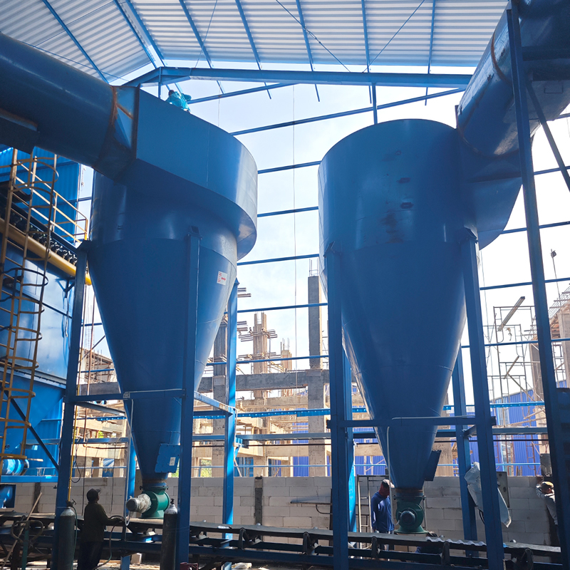
A cyclone dust collector (also known as a cyclone separator) is a widely used dry inertial dust removal device. Its core principle relies on centrifugal force generated by high-speed rotating dust-laden airflow to achieve gas-solid separation. Due to its simple structure, low cost, convenient maintenance, high temperature resistance, and wear resistance, it occupies an important position in industrial dust control—especially in sectors such as chemical fertilizer production, building materials, and chemical engineering. It is also one of the most commonly used primary dust removal equipment in processes like fertilizer drying and crushing.
Core Working Principle
The operation of a cyclone dust collector consists of four key stages, with an overall concise and efficient process:
- Airflow Introduction: Dust-laden gas (e.g., exhaust gas from chemical fertilizer drying) enters the cylindrical body through a tangential or volute-shaped inlet duct at a speed of 15-25 m/s, forming a stable downward-rotating airflow (called the “outer vortex”) inside the cylinder.
- Dust Separation: The rotating airflow generates strong centrifugal force (5-2500 times gravity), throwing dust particles (e.g., urea granules, compound fertilizer dust) mixed in the gas onto the cylinder wall. Since the mass of dust particles is much greater than that of gas, they lose inertia once they come into contact with the wall and slide down under the action of gravity.
- Airflow Reversal: When the airflow rotates to the bottom of the conical section, it is forced to change direction due to the shrinking space, forming an upward-rotating airflow (called the “inner vortex,” i.e., the clean gas core) that moves toward the top along the central area.
- Discharge of Dust and Gas: The sliding dust is collected in the hopper below the cone and discharged periodically through an airlock valve (to prevent air backflow from affecting separation efficiency). The purified gas is then discharged through the central exhaust pipe, completing the dust removal process.
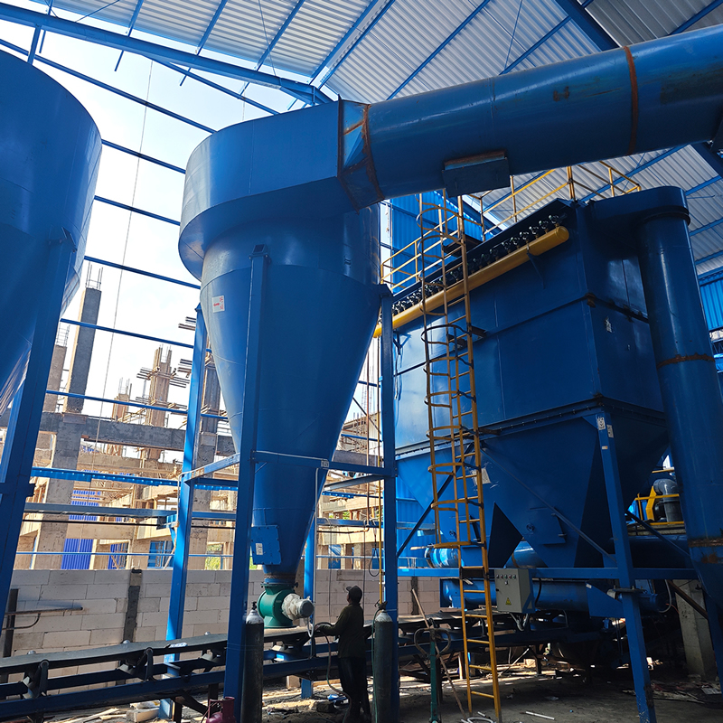
Basic Structure and Core Components
The equipment consists of 5 key components, and structural design directly affects dust removal efficiency and operational stability:
- Inlet Duct: Mostly adopts a tangential or volute design, with the core function of guiding airflow to form strong rotational motion. The inlet wind speed is usually controlled at 15-20 m/s (too low results in insufficient separation, while too high causes excessive pressure loss).
- Cylindrical Body: The main separation area. The diameter determines the air handling capacity (larger diameter means stronger processing capacity), and the height is typically 1.5-2.5 times the diameter to ensure sufficient time for dust to be thrown onto the wall.
- Conical Body: The airflow contraction zone, with a cone angle generally of 15°-20°. It enhances centrifugal force by reducing the rotation radius, while guiding dust to slide toward the hopper and reducing secondary dust emission.
- Exhaust Pipe: Located at the top of the cylindrical body, extending a certain length into the cylinder (usually 0.5-0.7 times the diameter) for discharging purified gas. The pipe diameter must match the air handling capacity to avoid airflow blockage.
- Hopper and Airlock Valve: The hopper is used to store collected dust. The airlock valve (e.g., star feeder) is a key auxiliary component that achieves “dust discharge without air leakage,” preventing external air from entering and damaging the negative pressure environment inside the cylinder, thus ensuring separation efficiency. (In the chemical fertilizer industry, the recovered dust can be directly returned to the production line through the hopper to reduce material waste.)
Key Technical Parameters (Common Ranges in the Chemical Fertilizer Industry)
- Air Handling Capacity: 500-100,000 m³/h per unit; 1,000-50,000 m³/h is commonly used in chemical fertilizer drying processes. The processing capacity can be expanded through parallel connection of multiple units.
- Dust Removal Efficiency: For coarse dust particles with a particle size ≥10 μm, the efficiency can reach 85%-95% (most chemical fertilizer dust is 5-50 μm, with good adaptability); for fine dust with a particle size <5 μm, the efficiency is only 60%-70% (requiring matching with secondary equipment such as bag filters).
- Pressure Loss: 500-1,500 Pa during normal operation. Lower pressure loss means lower energy consumption, which is usually reduced by optimizing the structure of the inlet duct and cylinder body.
- Inlet Wind Speed: A core control parameter, generally 12-25 m/s; 15-20 m/s is commonly used in the chemical fertilizer industry (balancing efficiency and energy consumption).
- Operating Temperature: Conventional materials (carbon steel) can withstand 200-400°C, meeting the processing requirements of chemical fertilizer drying exhaust gas (usually 80-150°C). Stainless steel can be selected for special working conditions.
- Applicable Dust Concentration: Inlet dust concentration ≤100 g/m³. The dust concentration of drying exhaust gas in chemical fertilizer production is mostly 10-50 g/m³, which can directly enter the equipment without pretreatment.
Core Applications in the Chemical Fertilizer Industry
Cyclone dust collectors are “basic dust removal units” in chemical fertilizer production, especially suitable for the following scenarios:
- Dust Removal in Drying Processes: In drying production lines for urea, compound fertilizer, organic fertilizer, etc., they serve as primary dust removal equipment, separating more than 80% of large-particle dust from exhaust gas. The recovered dust can be directly returned to the dryer or granulator, reducing material loss (material recovery rate in the chemical fertilizer industry can reach over 90%) and reducing the load on subsequent secondary dust removal equipment (e.g., bag filters).
- Dust Removal in Crushing/Screening Processes: A large amount of dust is generated during the crushing and screening of chemical fertilizer granules. The equipment can quickly separate dust, avoiding workshop dust pollution and ensuring the operating environment meets standards.
- Material Recovery: For valuable chemical fertilizer dust (e.g., urea powder, ammonium phosphate powder), efficient collection through the equipment realizes resource recycling and reduces production costs.
- Pretreatment Unit: When exhaust gas needs to meet higher environmental standards (e.g., dust emission concentration ≤10 mg/m³), the cyclone dust collector acts as a pre-treatment device to remove coarse particles first, then is combined with bag filters or electrostatic precipitators to form a “primary + secondary” combined dust removal system, balancing efficiency and economy.
Advantages and Disadvantages Analysis
Advantages
- Simple structure, no moving parts, low failure rate, and convenient installation and maintenance (workers in chemical fertilizer workshops can quickly master daily maintenance).
- Low cost and operating expenses (no need to consume filter media, water, or other consumables, only requiring the fan to provide power).
- Strong resistance to high temperature, wear, and corrosion, adapting to the high-temperature, dusty, and slightly corrosive exhaust gas environment in chemical fertilizer production.
- Large air handling capacity, suitable for large-scale production (a single unit can meet the needs of small and medium-sized drying lines, and parallel connection of multiple units can adapt to large-scale production lines).
- Convenient dust recovery without secondary pollution (dry dust removal, no need to treat sewage).
Disadvantages
- Low separation efficiency for fine dust (particle size <5 μm), making it difficult to meet strict environmental standards when used alone (requiring matching with secondary dust removal).
- Relatively high pressure loss and fan energy consumption (reasonable structural design is needed to reduce loss).
- Air handling capacity is limited by the equipment diameter, and the processing capacity of a single unit has an upper limit (large-scale production lines require parallel connection of multiple units, increasing floor space).
- Easily affected by airflow fluctuations; if the inlet wind speed is too high or too low, dust removal efficiency will decrease significantly.
Selection and Usage Notes
Selection Key Points
- Select based on air handling capacity: Choose equipment according to the exhaust gas emission of the chemical fertilizer production line (e.g., drying line), ensuring the equipment’s air handling capacity is ≥ the actual exhaust gas volume (with a 10%-20% margin reserved).
- Select based on dust particle size: If the dust is mainly coarse particles (≥10 μm), it can be used alone; if the proportion of fine dust is high, a “cyclone + bag filter” combined system should be selected.
- Consider installation space: Larger cylindrical diameter means stronger processing capacity but larger floor space. Choose an appropriate size based on workshop layout.
- Material selection: Carbon steel can be used for conventional chemical fertilizer dust (e.g., urea, compound fertilizer); for corrosive dust (e.g., monoammonium phosphate, potassium sulfate), stainless steel or corrosion-resistant coated materials should be selected.
- Supporting airlock valve: Must select an airlock valve with good sealing performance (e.g., star feeder) to avoid air leakage leading to decreased dust removal efficiency.
Usage and Maintenance Notes
- Regularly clean the hopper: Avoid excessive dust accumulation blocking the discharge port. It is recommended to inspect and clean it daily (adjust the frequency according to dust production).
- Check air tightness: Regularly inspect the connections of the inlet duct, cylinder body, and exhaust pipe to prevent air leakage (air leakage rate exceeding 5% will cause efficiency to drop by more than 30%).
- Control inlet wind speed: Adjust the wind speed through the fan to maintain it within the range of 15-20 m/s, avoiding airflow fluctuations.
- Prevent condensation: If the exhaust gas contains moisture (e.g., organic fertilizer drying), insulate the equipment to avoid condensation on the cylinder wall causing dust caking.
- Regular maintenance: Conduct a comprehensive inspection of the equipment annually, check the wear of the cylinder body (especially the inner wall of the cone), and replace or repair it in a timely manner if wear is severe.
With its high adaptability, low cost, and convenient maintenance, cyclone dust collectors have become indispensable basic dust removal equipment in chemical fertilizer production. They are particularly suitable as primary dust removal or pretreatment units in processes such as drying and crushing. When combined with secondary dust removal equipment, they can achieve efficient and environmentally friendly dust control goals.