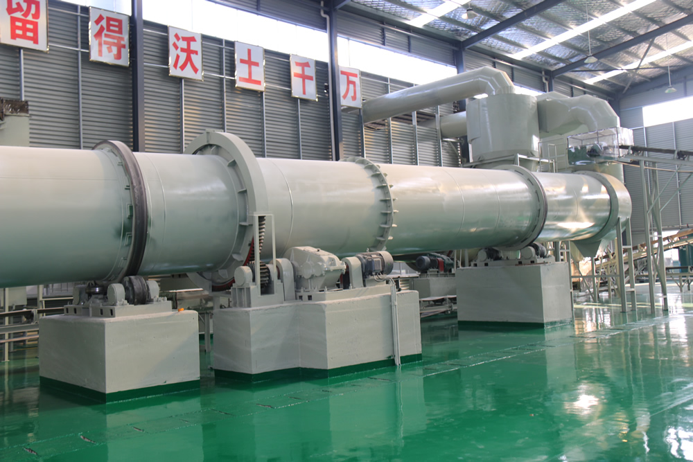
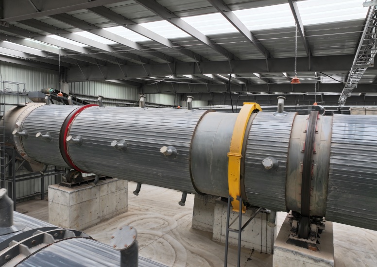
Installation site of rotary cooler
2025-12-18 11:12:01
By : root
The rotary drum cooler is a core equipment in industries such as fertilizer production, metallurgy, and building materials, used for continuous cooling of high-temperature materials. Its installation quality directly affects equipment operation stability and cooling efficiency. The installation shall follow the process of foundation acceptance → equipment positioning → component assembly → precision adjustment → commissioning, with specific steps as follows:
- Technical Documentation and Personnel Preparation
- Familiarize with equipment drawings, installation instructions, and foundation construction drawings, and clarify the installation dimensions and technical parameters of the equipment (such as drum inclination angle and support roller spacing).
- Deploy a professional installation team, including mechanical fitters, welders, and riggers, and prepare measuring tools such as total stations, levels, and torque wrenches.
- Foundation Acceptance and Treatment
- Inspect the strength, flatness, and dimensional deviation of the concrete foundation to ensure compliance with design requirements: foundation elevation error ≤ ±5mm, centerline deviation ≤ ±3mm, and surface flatness error ≤ 2mm/m.
- Clean oil stains, dust, and debris from the foundation surface, mark the longitudinal centerline (drum axis) and transverse centerline (support roller and thrust roller group axis) of the equipment according to the drawings, and embed center plates and reference points.
- Inspect the position, depth, and verticality of the reserved bolt holes in the foundation. The reserved holes shall be thoroughly cleaned without water accumulation or debris.
- Equipment Unpacking and Inspection
- Verify the equipment component list to confirm that components such as the drum, support roller group, thrust roller group, transmission system (motor, reducer, gear ring), and feed/discharge hood are complete and free from transportation damage.
- Inspect the processing precision of key components: tooth surface wear of the gear ring, roundness error of the support roller, and straightness error of the drum. If deformation exists, correct it in advance.
- Installation of Support Roller Group and Thrust Roller Group
- Leveling and Setting Out: Determine the installation position of the support roller group based on the foundation centerline, adjust the levelness of the support roller using shim plates, with a horizontal error ≤ 0.1mm/m.
- Elevation Control: Adjust the elevation difference between the front and rear support roller groups according to the designed drum inclination angle (usually 2°~4°) to ensure the drum is installed at the preset inclination angle.
- Thrust Roller Group Positioning: Install the thrust rollers on both sides of the drum’s tire ring, ensuring uniform clearance between the thrust rollers and the tire ring (usually 3~5mm) to prevent excessive axial movement of the drum.
- Secondary Grouting: After calibrating the positions of the support roller group and thrust roller group, perform secondary grouting on the equipment base. The grout shall be vibrated densely, and the anchor bolts shall be tightened after curing to the design strength.
- Hoisting and Positioning of the Drum
- Hoist the drum using a crane, and use soft slings to protect the drum surface from scratches during hoisting.
- Place the drum smoothly on the support roller group, ensuring uniform contact between the drum’s tire ring and the support rollers. Adjust the drum position to ensure the centerline of the tire ring is parallel to that of the support rollers.
- Measure the radial runout and axial movement of the drum: radial runout error ≤ 0.1% of the drum diameter, and axial movement controlled within ±10mm.
- Installation of Transmission System
- Install the reducer and motor, adjust the coaxiality of the motor and reducer (coaxiality error ≤ 0.1mm), and ensure the end face clearance of the coupling meets equipment requirements.
- Install the gear ring and pinion, ensuring gear meshing precision: addendum clearance = 0.25 times the modulus, backlash = 0.15~0.2 times the modulus, and meshing contact spots ≥ 60% along both tooth length and tooth height directions.
- Tighten the anchor bolts of the transmission system according to design standards to prevent loosening during operation.
- Installation of Feed/Discharge System
- Install the feed hood and discharge hood, adjust the connection clearance between the hood and the drum, and use flexible seals (such as asbestos rope and rubber sheet) to prevent material leakage and dust emission.
- Install the feed chute and discharge conveyor, ensuring the chute is aligned with the drum’s feed inlet, and the conveyor connects smoothly with the discharge outlet without material accumulation dead corners.
- Installation of Cooling Air System: Install fans, air ducts, and air volume control valves. Ensure air duct connections are sealed to prevent air leakage, and cooling air uniformly passes through the material layer along the drum axis.
- Installation of Lubrication System: Connect the lubricating oil circuit, fill with qualified lubricating oil (usually gear oil or hydraulic oil), and inspect the oil circuit for unobstructed flow to ensure lubrication of rotating components such as support rollers, thrust rollers, and gears.
- Installation of Electrical Control System: Install control cabinets, motor junction boxes, and sensors (such as temperature sensors and speed sensors). Wiring shall be standardized with proper grounding protection to prevent electric leakage.
- Static Adjustment
- Re-inspect the installation precision of each component: support roller levelness, drum inclination angle, gear meshing clearance, and seal clearance. Re-adjust if non-compliant.
- Manually rotate the drum to check for flexible rotation, no jamming or abnormal noise, and normal contact between the thrust rollers and the tire ring.
- No-load Commissioning
- Conduct no-load commissioning for no less than 4 hours. After starting the motor, check if the drum speed meets the design value, and the vibration value of the transmission system ≤ 0.1mm/s.
- Monitor bearing temperature: rolling bearing temperature ≤ 70℃, sliding bearing temperature ≤ 65℃. Stop the machine for inspection if temperature is abnormal.
- Inspect seal parts for air or material leakage, and adjust the sealing device to the optimal state.
- Load Commissioning
- After passing no-load commissioning, conduct load commissioning by gradually increasing the material feeding amount until reaching the rated processing capacity.
- Monitor the material cooling effect (temperature difference between inlet and outlet), equipment operating current, and vibration to ensure all indicators meet design requirements.
- Load commissioning shall last no less than 8 hours, and the equipment can be officially put into production only after stable operation.
- The adjustment of the support roller group is critical; ensure uniform force distribution on both sides of the support rollers to avoid excessive unilateral wear.
- The drum inclination angle directly affects material residence time. An excessively large angle results in insufficient cooling, while an excessively small angle easily causes material accumulation. Strictly adjust according to the design value.
- Regularly re-inspect the gear meshing precision of the transmission system. Stop the machine for adjustment immediately if abnormal noise occurs during operation.
- Establish an installation file after completion, recording the installation dimensions and adjustment data of each component for future maintenance.